|
click on image to
start animation:-
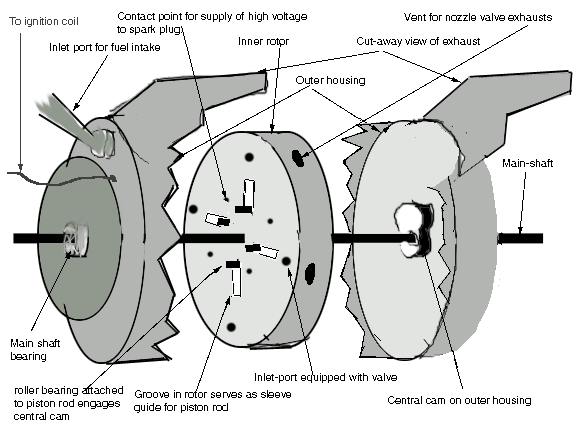
The image shows an alternative method for raising
and lowering of the pistons in order to compress fuel and
facilitate fuel/air intake. This design uses only 12 moving
parts in the whole engine. The central stationary cam maybe
modified in shape to include a cooling cycle for the
combustion chamber The central stationary cam is fixed onto
the two halves of the outer housing allowing free rotation of
the inner rotor. Click here to see a color coded schematic of the combustion cycle of the engine. Green = fuel intake cycle ; Yellow = Compression cycle ; Red = ignition , powerstroke and exhaust. Outlined at this site are two brilliantly innovative
engine designs , the first is the "Rotary Pulse Jet
Engine " Click here to see the latest version of this engine design This engine uses The Pulse Jet Technology (Click on
link to see how the pulse jet works.) , developed by the
Germans for their V2 bombers or "buzz" bombs , to power the
engine.
As is illustrated in the animation , the combustion
cycle of the Rotary Pulse Jet Engine works as follows:-
(1) A fuel- air mixture is forced into the combustion
chambers by the vacuum effect created bv the piston moving
down the cylinder , entry of fuel may also be aided by a
turbo-charger.
(2) The fuel- air mixture is then
compressed in a sealed environment by closing of the intake
valve and the upward movement of the piston.
(3) The
compressed fuel-air mixture is ignited resulting in rapid
expansion of the fuel.
(4) The heated fuel-air mixture
is explosively ejected through a nozzle resulting in the
rotation of the rotor in the direction of rotation.
The advantages of such an engine are that :-
(a) It eliminates the need for linear to rotary
conversion.
(b) It functions like a jet engine but
uses an intermittent instead of constant system of combustion,
resulting in lower fuel consumption.
( c ) A pulse -
jet engine has a much lower rpm 50 - 60 cycles per second ,
than a turbine
25,000 - 40000 rpm, which means that the
transmission is easier to link and design
(d) The
greatest advantage of the Rotary Pulse jet engine is that
every phase of its power output can be controlled and
therefore makes it ideal for linking to a computer to get
maximum performance.
The basic design of the Rotary
Pulse jet engine is extremely simple and would require only
40% of the parts needed in a conventional IC engine. The rotor
and shaft inclusive of the pistons could be made far lighter
than the weight needed to be moved in a conventional engine
such as the crankshaft , fly-wheel , cam-shaft , connecting
rods and so on , thereby giving the engine a much greater size
to power ratio.
Exploded view of the Rotary Pulse jet
engine:-

As can be seen in Figure 1. The Rotary Pulse Jet
Engine is very simple in design , it consists of a rotor ,
enabled for movement in one direction only , fixed to an axle
of which it is an integral part , revolving inside an outer
housing. The edge of the inner rotor contains variable volume
combustion chambers which contain spark plugs and pistons ,
the spark plugs are provided high voltage through the outer
housing in much the same way that the rotor in the dulco
system in conventional engines supplies high voltage to each
cylinder in turn , the pistons are used to facilitate intake
of fuel and air by creating a vacuum and to compress the fuel
-air mixture , they are not used to transmit power as in
conventional engines. Each combustion chamber is equipped with
an intake valve and an exhaust nozzle. The valves are opened
and closed through interaction of the rotor with the inner
surfaces of the outer housing, similarly the pistons also are
moved up and down the cylinders by the interaction of the piston shafts
with the stationary central cam , this means that there are only 12 moving parts in the whole engine , compare this with the more than 400 plus moving parts in an IC engine. The pistons are held in place by their position on the cam there is no need for ratchets,to hold them in place during ignition and to release them
during intake of fuel. Fuel is supplied to the inner rotor
through the outer housing and used fuel products are similarly
routed through the outer housing.Lastly , there have been a lot of questions on the size of the engine. Using 5" dia cylinders with a length of 3" and a compression ratio of 9.5 : 1 the size of the engine will be 18" in diameter , this can be reduced to 14 " if the combustion chamber is displaced relative to the cylinder. It must be noted that the cylinders and pistons are completely isolated from the combustion chamber through the use of a one way valve and the pistons do not therefore come under any mechanical or heat pressure. There are more details available on the FAQ page.
Click here to see the latest version of this engine design.
|


